In the realm of industrial ventilation, process engineering, and heavy-duty HVAC, the centrifugal fan—often referred to as a blower or squirrel-cage fan—stands as the foundational equipment for moving air against high resistance. While axial fans are designed to move high volumes of air at low pressure (similar to an airplane propeller), centrifugal fans are engineered to generate the immense static pressure required to push air through complex ductwork, dense filtration systems, and demanding industrial processes.
To understand why these machines are the workhorses of industrial air movement, we have to look past the basic definition and examine the aerodynamics, impeller geometry, and performance curves that dictate their operation.
The Physics of Operation: Kinetic Energy to Static Pressure
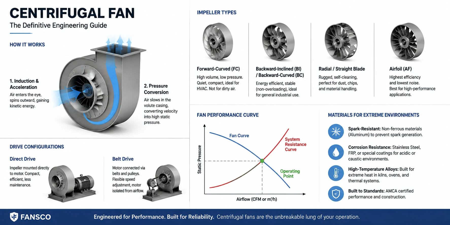
The fundamental operating principle of a centrifugal fan relies on a rotating impeller housed within a precisely engineered, snail-shaped volute (or scroll casing). The mechanics are highly efficient and rely on a two-step aerodynamic process:
- Induction and Acceleration: Air is drawn into the center of the rotating impeller, known as the “eye.” As the air enters, the spinning blades catch it and force it outward toward the fan’s perimeter. This radial acceleration, driven by centrifugal force, imparts immense kinetic energy (velocity pressure) to the airstream.
- Pressure Conversion: High-velocity air alone is not enough to overcome system resistance. As the accelerated air leaves the impeller blades, it strikes the inner contour of the scroll casing. The expanding geometric design of this casing slows the air down, efficiently converting the velocity pressure into static pressure. It is this high static pressure that allows the fan to exhaust air forcefully against the drag of ducts, dampers, and scrubbers.
Impeller Aerodynamics: Choosing the Right Blade Profile
The heart of any centrifugal fan is its wheel (impeller). The curvature and angle of the blades dictate the fan’s efficiency, noise levels, and suitability for specific environments. Engineers generally categorize centrifugal impellers into four primary designs:
1. Forward-Curved (FC)
Forward-curved blades cup the air in the direction of rotation. They are compact, run at relatively low RPMs, and are acoustically quiet. While highly effective for moving high volumes of clean air in low-pressure commercial HVAC applications (like rooftop units or furnaces), they are less energy-efficient than other profiles and are prone to particulate buildup, making them unsuitable for dirty airstreams.
2. Backward-Inclined (BI) and Backward-Curved (BC)
These blades tilt away from the direction of rotation. Operating at much higher speeds than FC fans, backward-inclined designs offer superior energy efficiency. Crucially, they possess a non-overloading horsepower characteristic. This means that if the system pressure suddenly drops, the motor will not draw excessive current and burn out. These are the industry standard for general industrial ventilation and forced-draft applications.
3. Radial / Straight Blade
Radial blades extend perfectly straight from the central hub. While they offer the lowest aerodynamic efficiency of the group, their rugged, open design is self-cleaning. Centrifugal force naturally prevents dust, wood chips, and sticky particulates from adhering to the blades. Therefore, radial fans are the undisputed choice for pneumatic conveying, dust collection, and extreme material handling.
4. Airfoil (AF)
Airfoil blades feature a streamlined, teardrop shape identical to an airplane wing. This is the most efficient centrifugal fan design available, dramatically reducing air turbulence and noise. Because of the precision required in manufacturing, AF fans have a higher capital cost, but they offer the fastest ROI in large-scale, continuous-duty applications (like power plant boilers or massive cleanroom setups) due to massive energy savings over time.
Direct Drive vs. Belt Drive Mechanics
Beyond the blade design, the way the motor is connected to the impeller dramatically impacts maintenance, efficiency, and footprint. Industrial centrifugal fans utilize two main drive configurations:
- Direct Drive: The impeller is mounted directly onto the motor shaft. This eliminates transmission losses, reduces the physical footprint, and removes the need for belt maintenance. However, the fan speed is locked to the motor speed unless controlled by a Variable Frequency Drive (VFD).
- Belt Drive: The motor is connected to the fan shaft via pulleys and belts. This setup allows engineers to fine-tune the fan’s RPM by simply changing the pulley ratios, providing immense flexibility for systems where air volume requirements might change. Additionally, the motor is isolated from the airstream, protecting it from extreme heat or corrosive gases passing through the fan casing.
Understanding Fan Performance and System Resistance
In professional engineering, a centrifugal fan is never selected in a vacuum. It must be matched perfectly to the system it serves. Every ductwork system has a System Resistance Curve—the exact amount of pressure required to move a specific volume of air through it.
Conversely, every centrifugal fan has a specific Fan Performance Curve, mapped out by the manufacturer, detailing how much pressure it can generate at a given airflow (CFM or m³/h). The precise point where the fan’s curve intersects the system’s resistance curve is the Operating Point. Proper fan selection ensures that this operating point falls within the fan’s peak efficiency zone, minimizing energy consumption, reducing vibration, and preventing aerodynamic stall.
Materials of Construction for Extreme Environments
Standard commercial fans are fabricated from carbon steel or galvanized steel. However, centrifugal fans are often deployed in punishing industrial environments that require specialized construction:
- Spark-Resistant Construction: For exhausting volatile gases (like in chemical plants or paint booths), fans must be built to AMCA (Air Movement and Control Association) spark-resistant standards, utilizing non-ferrous materials like aluminum to prevent spark generation.
- Corrosion Resistance: When moving acidic or caustic fumes, internal components are often coated with specialized epoxies, or the entire fan is fabricated from 304/316 Stainless Steel or Fiberglass Reinforced Plastic (FRP).
- High-Temperature Alloys: Fans integrated into kilns, ovens, or thermal oxidizers often feature heat slingers, specialized bearings, and impellers made from high-nickel alloys to maintain structural integrity at extreme temperatures.
Conclusion: The Fansco Perspective
Specifying a centrifugal fan is an exercise in precision. It requires calculating air density, altitude, static pressure, and particulate load to ensure the equipment survives its intended lifespan. Whether you are designing a high-pressure pneumatic conveying line, upgrading a commercial HVAC matrix, or exhausting hazardous fumes, the right centrifugal fan acts as the unbreakable lung of your operation.
At Fansco, we specialize in bridging the gap between aerodynamic theory and industrial reality. By understanding the rigorous engineering behind centrifugal blowers, you are empowered to make procurement decisions that maximize efficiency, ensure compliance, and minimize operational downtime.