In modern industrial thermal management, a cooling fan is no longer just a spinning piece of plastic; it is an intelligent node within a complex digital ecosystem. For electrical engineers and system integrators, understanding how to communicate with these nodes is critical. Sourcing a fan with the correct physical dimensions but the wrong pinout will lead to uncontrolled RPMs, burned motherboards, or a complete blind spot in system telemetry.
This technical bulletin decodes the entire spectrum of fan wiring matrices, moving from standard Direct Current (DC) pinouts to the complex architecture of intelligent Electronically Commutated (EC) systems.
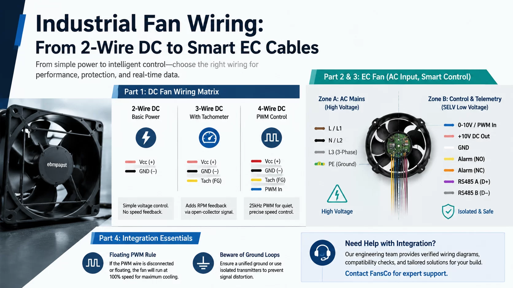
Part 1: The DC Fan Wiring Matrix (2, 3, and 4-Wire)
DC fan wiring dictates exactly how much control and feedback the host motherboard possesses. Upgrading from one tier to the next represents a fundamental shift in control theory.
1. Two-Wire DC: Basic Voltage Regulation
Consisting solely of Vcc (Power) and GND (Ground), this is the most primitive setup.
- Control Logic: Speed is controlled via linear voltage regulation (e.g., dropping a 12V supply to 7V).
- Engineering Flaw: Dropping voltage drastically reduces the motor’s starting torque. Furthermore, the system is entirely “blind.” If dust locks the rotor, the motherboard continues sending power, oblivious to the failure until the main CPU overheats.
2. Three-Wire DC: Open-Collector Telemetry
This configuration introduces a third wire: the Tachometer (Frequency Generator / FG).
- Signal Mechanics: This is typically an “Open-Collector” output. The host motherboard must provide a pull-up resistor to a logic voltage (like 3.3V or 5V). As the internal Hall-effect sensor detects rotor magnets, it pulls this signal to ground, creating a square wave (typically 2 pulses per revolution) to report exact RPM.
- Limitation: While the system gains real-time telemetry, active speed control still relies on inefficiently manipulating the main voltage.
3. Four-Wire DC: Precision High-Frequency PWM
The definitive standard for telecom, servers, and high-density computing. It adds a dedicated PWM (Pulse Width Modulation) input wire.
The PWM Advantage: The fan receives a constant, unadulterated 12V, 24V, or 48V on its power wires, ensuring maximum torque is always available. The 4th wire receives a 5V logic signal switching on and off at a high frequency—typically 25 kHz. Because 25 kHz is above human hearing, it eliminates annoying “motor whine.” By altering the Duty Cycle, the internal IC seamlessly adjusts the RPM from 10% to 100%.
Part 2: The AC Paradox and EC Technology
Traditional Alternating Current (AC) fans (using shaded-pole or split-capacitor motors) are tied directly to the grid frequency (50Hz or 60Hz). They usually feature just two wires (Live and Neutral) and run at a single, fixed speed. Attempting to slow them down using a Triac dimmer (clipping the AC sine wave) induces massive electrical harmonics, causing the motor to hum violently and overheat.
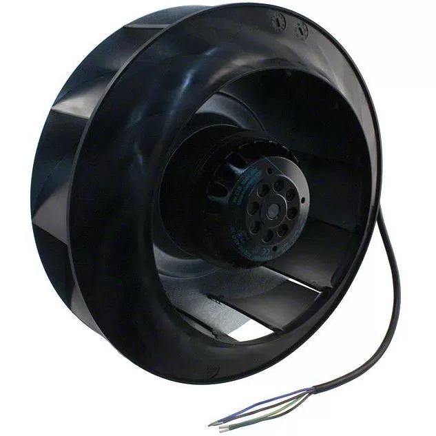
So, why do premium industrial AC fans—like advanced ebmpapst models—feature a massive wiring harness containing 7, 8, or even 10+ wires? They plug into the exact same AC wall power, yet look like a data cable.
The answer is EC (Electronically Commutated) Technology.
Part 3: Decoding the “Spaghetti Cable” of an EC Fan
An EC fan acts as a DC fan disguised as an AC fan. It takes high-voltage AC mains, internally rectifies it to DC, and uses an onboard microprocessor to drive a highly efficient brushless motor. By strict industrial safety standards (SELV), the wires emerging from an EC fan are divided into two galvanically isolated zones:
Zone A: High-Voltage Mains (Power)
This heavy-gauge section handles the raw grid power.
- Single-Phase (115V/230V): Live (L), Neutral (N), and Protective Earth (PE).
- Three-Phase (400V/480V): L1, L2, L3, and PE.
Zone B: SELV Control & Telemetry (Low Voltage)
This is the nervous system of the EC fan. Wiring high voltage into these pins will instantly destroy the internal microprocessor.
| EC Control Wire | Engineering Function & System Application |
|---|---|
| 0-10V / PWM Input | Analog control. A PLC outputs a 0-10V signal to command the fan’s PID loop. 1V commands low speed, while 10V commands 100% capacity. |
| +10V DC Output | The fan generates its own clean 10V logic supply. Engineers use this to power external sensors or wire a manual potentiometer directly to the fan without an external power supply. |
| Alarm Relay (NO/NC) | A physical dry-contact relay inside the fan. If diagnostics detect an over-temperature state or locked rotor, the relay trips, triggering a hardwired safety shutdown in the host PLC. |
| RS485 Modbus RTU | The ultimate digital bus. Allows engineers to daisy-chain multiple fans, assign IP/MAC addresses, remotely dictate RPM, read exact wattage, and monitor motor temps for predictive maintenance. |
Part 4: Crucial Integration Traps
Even with the correct pinout, engineers frequently encounter integration failures. Keep these rules in mind:
- The Floating PWM Pin Rule: By industry safety design, if the PWM wire on a 4-wire DC or an EC fan is severed or left disconnected (floating), the fan defaults to 100% maximum speed. This ensures the system receives maximum cooling during a control wire failure rather than shutting down.
- Beware of Ground Loops: When integrating 0-10V analog signals across long distances in a factory, differences in ground potential between the master PLC and the fan can distort the signal. Always ensure a unified ground plane or utilize isolated signal transmitters.
Architecting Your Control Systems? We Can Help.
Translating legacy AC relay logic to modern EC Modbus networks requires precision. A single misinterpreted pinout can halt production lines. Do not leave your thermal management integration to guesswork.
Reach out to the FansCo technical engineering team. We provide verified ebmpapst wiring diagrams, interface compatibility checks, and tailored procurement strategies for your custom builds.